Front I/O
Code
Arduino project with utils and script for driving all LEDs, buttons and MLB front I/O headers for driving Xserve front I/O devices: https://github.com/KevinMidboe/xserve-io.
Pinout
There is a single cable that controls four parts, each half side of I/O LED and center column of blue LEDs.
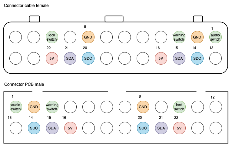
This cable allows us to communicate with 4 chips using two data lines, audio & service switch, case switch and (yet to be documented) compute LEDs
How we got here
Measure out the ground and power signals by comparing with other chips on board. E.g. we find [SAA1064T] datasheet, locate the GND (Vee) and 5V (Vcc) and measure connectivity (0 ohm resistance) between chip pins and cable pins. This gives us pins GND 2 & 8 and PWR 16 & 22.
We keep doing this for SCL & SDA pins on SAA1064T chip and find pins 14 & 15 and 20 & 21 are I2C clock and data pins for each chip.
Finding i2c chip address
SAA1064T
Reading the datasheet for SAA1064T chip we find that: "This results in the corresponding valid addresses HEX 70, 72, 74 and 76 for writing and 71, 73, 75 and 77 for reading. All other addresses cannot be acknowledged by the circuit". Giving us a clue what we are looking for, i2c addresses 0x70, 0x72 or 0x74.
PCA9554
asdf
Code example finding i2c addresses
We can test the following addresses manually or use the following code snippet:
This sketch tests standard 7-bit addresses.
Devices with higher bit address might not be seen properly.*/
#include <Wire.h>
void setup() {
Wire.begin();
Serial.begin(9600);
while (!Serial);
Serial.println("\nI2C Scanner");
}
void loop() {
byte error, address;
int nDevices;
Serial.println("Scanning...");
nDevices = 0;
for (address = 1; address < 127; address++ ) {
Wire.beginTransmission(address);
error = Wire.endTransmission();
if (error == 0) {
Serial.print("I2C device found at address 0x");
if (address < 16)
Serial.print("0");
Serial.print(address, HEX);
Serial.println(" !");
nDevices++;
}
else if (error == 4) {
Serial.print("Unknown error at address 0x");
if (address < 16)
Serial.print("0");
Serial.println(address, HEX);
}
}
if (nDevices == 0)
Serial.println("No I2C devices found\n");
else
Serial.println("done\n");
delay(5000);
}
i2c multiplexing with TCA9548
We have two sets of chips, one for left and one for right where we have two different i2c chips on each side for controlling lights. Since the chips controlling their respective parts have the same address for each side, we can't distinguish them from each other. To handle this we use a i2c multiplexer to selectively communicate with one half at a time, switching TCA9548 between two different output ports.
Code example finding i2c ports
To verify wiring, connection, output ports and device addresses run the following script:
* TCA9548 I2CScanner.ino -- I2C bus scanner for Arduino
*
* Based on https://playground.arduino.cc/Main/I2cScanner/
*
*/
#include "Wire.h"
#define TCAADDR 0x70
void tcaselect(uint8_t i) {
if (i > 7) return;
Wire.beginTransmission(TCAADDR);
Wire.write(1 << i);
Wire.endTransmission();
}
// standard Arduino setup()
void setup()
{
while (!Serial);
delay(1000);
Wire.begin();
Serial.begin(9600);
Serial.println("\nTCAScanner ready!");
for (uint8_t t=0; t<8; t++) {
tcaselect(t);
Serial.print("TCA Port #"); Serial.println(t);
for (uint8_t addr = 0; addr<=127; addr++) {
if (addr == TCAADDR) continue;
Wire.beginTransmission(addr);
if (!Wire.endTransmission()) {
Serial.print("Found I2C 0x"); Serial.println(addr,HEX);
}
}
}
Serial.println("\ndone");
}
void loop()
{
}
SAA1064T data for driving center IO LED stack
Center IO stack is a stack of 24 LED's, 23 blue and 1 green for ethernet activity. These are duplicated next to each other and driven by each their SAA1064T chips. Earlier we found the i2c address and just by playing around figured out that 4 segments of 1 byte binary values are used to set ship register.
Serial.println("filling columns");
Wire.beginTransmission(saa1064);
Wire.write(1);
Wire.write(0x7F); // 127 - 1111111
Wire.write(0x7F); // 127 - 1111111
Wire.write(0x7F); // 127 - 1111111
Wire.write(0x1F); // 31 - 11111
Wire.endTransmission();
colsFilled = 1;
}
-- Here the last byte we send only is 5 bits since we only have 5 LEDs instead of 6 to address (total of 24). Also note that we start the transmission with a single bit. --
Pinouts voltages from MLB
Powered off:
- PWR fail LED - 0.00 V
- UID LED - 4.5V
- OH/Fan fail LED - 4.72 V
- NIC1 LED - 0.8 - 2.6 V
- NIC2 LED - 2.95 V
- UID SW - 2.8V
- HDD LED - 0.00 V
- Power LED P3V3 - 0.00V
- Power LED - 0.00 V after unplug grows
Powered on:
- PWR tail LED - 3.47 V
- UID LED - 4.85V
- OH/Fan failed LED - 5 V
- NIC 1 LED - 1.2 - 2.9 V
- NIC 2 LED - 3.2 V
- UID SW - 3V
- HDD LED - 3 V
- Power LED P3V3 - 3.30V
- Power LED - 0.87 V
Controlling top I/O LED
On the top row we have the following input/output devices in order from left to right;
Left side:
- physical lock
- lock LED
- warning/service button
- warning/service LED
- locate button
- power LED (red & green)
- fan LED (red & green)
- temperature LED (red & green)
- compute LED (unknown)
Right side:
- power LED (red & green)
- fan LED (red & green)
- temperature LED (red & green)
- compute LED (unknown)
- lock switch
Each sides bank of LEDs are driven by each their PCA9554 shift register. The registers represent the following LEDs: (Note that Lock LED is only present for the LEFT side)
| Register | 1 | 2 | 3 | 4 | 5 | 6 | 7 |
|---|---|---|---|---|---|---|---|
| Device | Power LED Green | Power LED Red | Fan LED Green | Fan LED Red | Temperature LED Green | Temperature LED Red | Lock LED |
To control each LED we shift either a 0 to turn off or 1 to turn on. Since each device shares a single red/green LED (power LED green & power LED red) setting both to 1 at the same time will always leave it red. That is when power LED green and power LED red are both enabled, red always takes precedence.
Use following script to power LEDs one at a time:
PCA9554 ioCon1(0x24); // Create an object at this address
uint8_t mapIO = 0b10000000;
void shiftL() {
mapIO = (mapIO << 1) | ((mapIO & 0x80) >> 7);
}
void write() {
Serial.println("writing to PCA9554 device");
for (int i = 0; i < 8; ++i) {
ioCon1.digitalWrite(i, (mapIO & (1 << i)) ? 0 : 1);
}
}
void setup()
{
Serial.begin(9600);
Serial.println("Setup");
ioCon1.portMode(ALLOUTPUT);
}
void loop()
{
write();
shiftL();
delay(500);
}
Controlling middle IO strip
0 = 0000
1 (green) = 0001
2 = 0010
1 + 2 = 0011
3 = 0100
There are 4 words, each containing 7 data bits. They do not
Front I/O LED Column Address Map
| Address Range (Binary) | Address Range (hex) | Size | Description |
| 0-7 | 00-07 | 1 byte | Ethernet indicator and LEDs register 1 |
| 8-15 | 08-0F | 1 byte | LEDs register 2 |
| 16-23 | 10-17 | 1 byte | LEDs register 3 |
| 24-31 | 18-1F | 1 byte | LEDs register 4 |
| Registers | LEDs Controlled | Count | Address Range (hex) | Description |
| Register 1 | 1 2 4 6 8 10 12 | 7 | 00-07 | LED 1 ethernet indicator, even bottom half |
| Register 2 | 3 5 7 9 11 13 | 6 | 08-0F | Odd LED top half |
| Register 3 | 14 16 18 20 22 23 24 | 7 | 10-17 | Even LED bottom half |
| Register 4 | 15 17 19 21 | 4 | 18-1F | Odd LED top half |
| bits (1 byte per register) | |||||||||
| Controls device | Register | 7 | 6 | 5 | 4 | 3 | 2 | 1 | 0 |
| Ethernet LED | Register 1 | 0 | 0 | 0 | 0 | 0 | 0 | 0 | 1 |
| LED 1 | Register 1 | 0 | 0 | 0 | 0 | 0 | 0 | 1 | 0 |
| LED 2 | Register 2 | 0 | 0 | 0 | 0 | 0 | 0 | 1 | 0 |
| LED 3 | Register 1 | 0 | 0 | 0 | 0 | 0 | 1 | 0 | 0 |
| LED 4 | Register 2 | 0 | 0 | 0 | 0 | 0 | 1 | 0 | 0 |
| LED 5 | Register 1 | 0 | 0 | 0 | 0 | 1 | 0 | 0 | 0 |
| LED 6 | Register 2 | 0 | 0 | 0 | 0 | 1 | 0 | 0 | 0 |
| LED 7 | Register 1 | 0 | 0 | 0 | 1 | 0 | 0 | 0 | 0 |
| LED 8 | Register 2 | 0 | 0 | 0 | 1 | 0 | 0 | 0 | 0 |
| LED 9 | Register 1 | 0 | 0 | 1 | 0 | 0 | 0 | 0 | 0 |
| LED 10 | Register 2 | 0 | 0 | 1 | 0 | 0 | 0 | 0 | 0 |
| LED 11 | Register 1 | 0 | 1 | 0 | 0 | 0 | 0 | 0 | 0 |
| LED 12 | Register 2 | 0 | 1 | 0 | 0 | 0 | 0 | 0 | 0 |
| LED 13 | Register 3 | 0 | 0 | 0 | 0 | 0 | 0 | 0 | 1 |
| LED 14 | Register 4 | 0 | 0 | 0 | 0 | 0 | 0 | 0 | 1 |
| LED 15 | Register 3 | 0 | 0 | 0 | 0 | 0 | 0 | 1 | 0 |
| LED 16 | Register 4 | 0 | 0 | 0 | 0 | 0 | 0 | 1 | 0 |
| LED 17 | Register 3 | 0 | 0 | 0 | 0 | 0 | 1 | 0 | 0 |
| LED 18 | Register 4 | 0 | 0 | 0 | 0 | 0 | 1 | 0 | 0 |
| LED 19 | Register 3 | 0 | 0 | 0 | 0 | 1 | 0 | 0 | 0 |
| LED 20 | Register 4 | 0 | 0 | 0 | 0 | 1 | 0 | 0 | 0 |
| LED 21 | Register 3 | 0 | 0 | 0 | 1 | 0 | 0 | 0 | 0 |
| LED 22 | Register 3 | 0 | 0 | 1 | 0 | 0 | 0 | 0 | 0 |
| LED 23 | Register 3 | 0 | 1 | 0 | 0 | 0 | 0 | 0 | 0 |
Controlling center LED columns
There are a total of 4 banks of addressable LED's 12 each of the total 48.
Script for writing all permutations to display:
byte saa1064 = 0x3B; // define the I2C bus address for our SAA1064 (pin 1 to GND) ****
void setup()
{
Wire.begin(); // start up I2C bus
}
void write(int value) {
Wire.beginTransmission(saa1064);
Wire.write(1);
Wire.write(value);
Wire.write(value);
Wire.write(value);
Wire.write(value);
Wire.endTransmission();
}
void loop() {
for (int value = 0; value < 127; value++) {
write(value);
delay(300);
}
}
Since LED positions don't map sequentially with LED number we can't address them in 10-base form, but we can define each LED in binary and use OR operator to display LEDs we want.
#define TCAADDR 0x70
byte saa1064 = 0x3B; // define the I2C bus address for our SAA1064
byte bank1;
byte bank2;
byte bank3;
byte bank4;
byte activityLED = 0b00000001;
byte leds[23][4] = {
{0b00000010, 0b00000000, 0b00000000, 0b00000000}, // 1
{0b00000000, 0b00000010, 0b00000000, 0b00000000}, // 2
{0b00000100, 0b00000000, 0b00000000, 0b00000000}, // 3
{0b00000000, 0b00000100, 0b00000000, 0b00000000}, // 4
{0b00001000, 0b00000000, 0b00000000, 0b00000000}, // 5
{0b00000000, 0b00001000, 0b00000000, 0b00000000}, // 6
{0b00010000, 0b00000000, 0b00000000, 0b00000000}, // 7
{0b00000000, 0b00010000, 0b00000000, 0b00000000}, // 8
{0b00100000, 0b00000000, 0b00000000, 0b00000000}, // 9
{0b00000000, 0b00100000, 0b00000000, 0b00000000}, // 10
{0b01000000, 0b00000000, 0b00000000, 0b00000000}, // 11
{0b00000000, 0b01000000, 0b00000000, 0b00000000}, // 12
{0b00000000, 0b00000000, 0b00000001, 0b00000000}, // 13
{0b00000000, 0b00000000, 0b00000000, 0b00000001}, // 14
{0b00000000, 0b00000000, 0b00000010, 0b00000000}, // 15
{0b00000000, 0b00000000, 0b00000000, 0b00000010}, // 16
{0b00000000, 0b00000000, 0b00000100, 0b00000000}, // 17
{0b00000000, 0b00000000, 0b00000000, 0b00000100}, // 18
{0b00000000, 0b00000000, 0b00001000, 0b00000000}, // 19
{0b00000000, 0b00000000, 0b00000000, 0b00001000}, // 20
{0b00000000, 0b00000000, 0b00010000, 0b00000000}, // 21
{0b00000000, 0b00000000, 0b00100000, 0b00000000}, // 22
{0b00000000, 0b00000000, 0b01000000, 0b00000000} // 23
};
void setup()
{
Serial.begin(9600);
Wire.begin(); // start up I2C bus
Serial.println("setting up ports");
}
void tcaselect(uint8_t i) {
if (i > 7) return;
Wire.beginTransmission(TCAADDR);
Wire.write(1 << i);
Wire.endTransmission();
}
void selectLeft() { tcaselect(2); }
void selectRight() { tcaselect(1); }
void write() {
Wire.beginTransmission(saa1064);
Wire.write(1);
Wire.write(bank1);
Wire.write(bank2);
Wire.write(bank3);
Wire.write(bank4);
Wire.endTransmission();
}
void resetBanks() {
bank1 = 0;
bank2 = 0;
bank3 = 0;
bank4 = 0;
}
void displayNumber(int number) {
bank1 = leds[number - 1][0];
bank2 = leds[number - 1][1];
bank3 = leds[number - 1][2];
bank4 = leds[number - 1][3];
}
void displayUpToNumber(int number) {
for (int i = 0; i < number; i++) {
bank1 = bank1 | leds[i][0];
bank2 = bank2 | leds[i][1];
bank3 = bank3 | leds[i][2];
bank4 = bank4 | leds[i][3];
}
}
void computeEthernetActivity() {
bank1 = bank1 | activityLED;
}
void loop() {
resetBanks();
delay(10);
displayUpToNumber(15);
computeEthernetActivity();
selectLeft();
write();
delay(2);
selectRight();
write();
delay(1000);
}
Missing pieces, TODO
- how to control compute LED in top IO row
- control warning button LED

